In this blog post, I have covered, How I have configured BGP peering between NSX-T Edge and Cisco 1000v virtual router.
I have explained my lab environment in my previous blog post
I have already deployed following virtual components on Physical Server.
1. Three ESX Servers (version 7.0 U1)
2. One vCenter (version 7.0 U3)
3. One DNS Server (Cent-OS)
4. One NSX Manager (version 3.1)
5. One NSX Edge (Version 3.1)
6. One Cisco CSR Router
7. Linux based test VMs and Windows VMs (2016)
Physical Topology

Logical Topology

In above logical topology, I have configured Windows VM with ip (192.168.10.100) and it’s default gateway is Cisco 1000v (192.168.10.2), Here is the configuration details for Cisco 1000v. Especially 2 interfaces, one is facing windows VM and other one is facing NSX-T Edge Gateway.


Ping works well between 1000v (192.168.10.2) and Windows VM (192.168.10.100)
Here is quick glimpse of vSphere Compute and Network configurations.

Here is the configuration specs for NSX-T. I have prepared following 3 ESXi hosts with NSX-T.
In NSX Configuration column is showing success status for each ESXi host. It means NSX vibs are successfully installed in ESXi hosts

I have selected labesx-1.vnetworkcloud.com, Click on Action menu to check overlay configuration.
Type :- NSX-VDS
Mode :- Standard
Name :- NSX-VDS
Transport Zone :- nsx-overlay-transportzone (it covers 3 ESXi & 1 Edge Gateway)
Uplink Profile :- ESX-hostuplink-profile
TEP IP Segment :- Static IP Pool (192.168.1.80-85)

Single NSX-T Edge Service gateway prepared with NSX vibs and TEP IP Configured on it. (I have not configured edge cluster because of limited underline resources)

I have selected nsx-edge1, Click on Action menu to check overlay configuration.

Until now I have created 2 transport zones, overlay back TZ spans on 3 ESXi and Edge-1. VLAN back TZ spans only on Edge-1.

ESXi uplink profile configuration specs

Overlay and VLAN Back Configuration specs.

I just have single vCenter deployed in this environment and i have added that vCenter into the compute section of NSX-T.

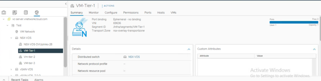
From here, I have deployed NSX-T segments followed with Tier0/1 Gateway deployment.
3 logical segments (VM-Tier-1/2/3) are overlay backed are connected to tier1 router and 1 Edge-uplink1 is VLAN uplink for Edge-1

Tier-0 GW deployed

Configuration of Edge Interface from Interfaces section.
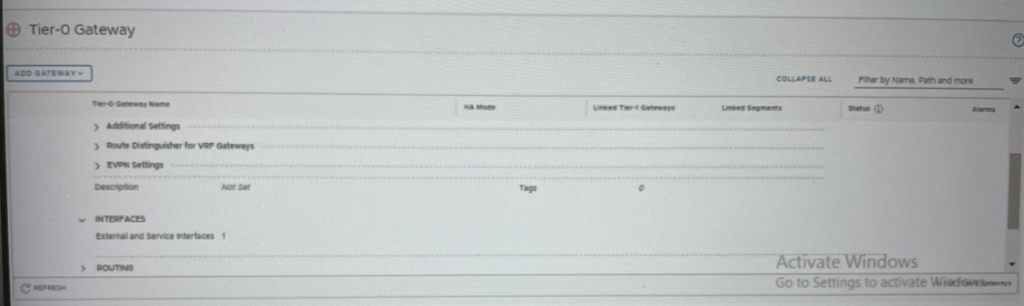

We have configured Edge uplink interface 100.100.100.1/29 facing Cisco 1000v Router.
Next few screen-shot of BGP Configuration on Tier-0 GW.


Once BGP neighbors are configured, we need to redistribute the connected tier-0 segments


BGP Configuration and redistribution is completed on tier-0.
Now I have configured BGP on Nexus 1000v.

From here, I have deployed tier-1 gw and hooked tier-1 gw to tier-0 gw

This Tier-1 gw connected networks should be advertise if you want to communicate overlay segments with outside of NSX Network.

I have completed Tier0/1 and 1000v Configuration Part. Let’s explore the NSX CLI.
NSX command line verification on edge, Login to NSX-Edge (192.168.1.140) and get the logical routers details by running below command.


Command to list learnt BGP routes in NSX-T Edge.


Now I have checked Cisco 1000v route table. I can see routes learnt from NSX Segments


Ping connectivity test from Windows VM (192.168.10.100) to segments behind tier-1 gw

Here I have completed my second blog post on NSX-T Configuration in home LAB.
Next blog I will post NSX-T troubleshooting.


